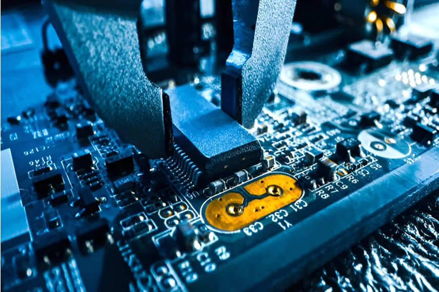
Printed circuit boards (PCBs) are at the heart of nearly every electronic device, but not all PCBs serve the same function. Among the most important types is the Control PCB, which acts as the brain behind a machine or system’s operations. Understanding the function of a control PCB and how it’s produced through the electronic manufacturing process is essential for designers, engineers, and OEMs aiming for high-performance and reliability.
In this guide, we’ll explore what a control PCB is, its role in electronic systems, and how it’s manufactured using modern techniques and quality standards.
What Is a Control PCB?
A Control PCB (Control Printed Circuit Board) is a specialized circuit board that manages and coordinates the operation of various components within an electronic system. It typically integrates microcontrollers, programmable logic devices, power management modules, and communication interfaces to process inputs, execute logic, and control outputs.
Think of it as the central nervous system of a device—it receives input signals, makes logical decisions, and sends output signals accordingly. Control PCBs are widely used in:
- Industrial automation systems
- HVAC controllers
- Smart home devices
- Robotics
- Automotive electronic control units (ECUs)
- Consumer electronics like washing machines, microwaves, and smart thermostats
In each of these applications, the control PCB ensures correct and efficient operation according to pre-programmed logic or user inputs.
Key Features of a Control PCB
A control PCB is engineered to handle a wide range of operational conditions and complex control logic. Key characteristics include:
-
Programmable Components
Control PCBs usually feature programmable ICs such as microcontrollers, FPGAs, or digital signal processors (DSPs), enabling flexible logic execution.
-
Input/Output Interfaces
These boards manage both analog and digital inputs/outputs to interact with sensors, actuators, relays, and other devices.
-
Power Regulation
Integrated voltage regulators, filters, and protection circuits ensure stable power to sensitive components.
-
Communication Protocols
Modern control PCBs support interfaces like UART, SPI, I2C, CAN, and Ethernet for internal and external data communication.
-
High Reliability
Because control PCBs often handle mission-critical logic, they must be designed with robust components, EMI protection, and high-quality materials.
Overview of the Electronic Manufacturing Process for Control PCBs
Producing a reliable control PCB requires a precise and quality-controlled electronic manufacturing process. This multi-step process transforms a PCB design into a fully assembled and functional board ready for integration into a final product.
Step 1: Design and Layout
The process starts with designing the schematic and PCB layout. This involves:
- Selecting suitable components
- Creating electrical connections
- Optimizing trace routing for signal integrity and thermal performance
Design software like Altium Designer, Eagle, or KiCad is commonly used at this stage.
Step 2: PCB Fabrication
Once the design is complete, it is sent for fabrication. Key steps include:
- Layer imaging: Applying circuit patterns to copper-clad laminates
- Etching: Removing excess copper to define circuit traces
- Drilling: Creating holes for through-hole components and vias
- Plating and surface finish: Adding copper to vias and applying finishes like ENIG or HASL for solderability
For control PCBs, multilayer boards are often used to accommodate complex routing and ground/power planes.
Step 3: Component Procurement
Simultaneously, components such as microcontrollers, connectors, resistors, and capacitors are sourced. Choosing reliable, long-life components is critical for control PCBs that operate in demanding environments.
Step 4: PCB Assembly
The PCB assembly process involves mounting and soldering components onto the fabricated board using:
- Surface Mount Technology (SMT) for placing small components automatically
- Through-Hole Technology (THT) for stronger mechanical support, often used in connectors or power components
Reflow soldering (for SMT) and wave soldering (for THT) are common techniques used in the assembly stage.
Step 5: Inspection and Quality Control
This stage includes:
- Automated Optical Inspection (AOI) to catch placement or soldering errors
- X-ray Inspection for BGA or hidden-joint components
- In-Circuit Testing (ICT) to verify component functionality
- Functional Testing using custom setups to simulate real-world conditions
Control PCBs require thorough inspection due to their role in managing device functionality.
Step 6: Programming and Configuration
If the control PCB includes programmable components, firmware is loaded during or after assembly. Manufacturers often include a debugging interface for future software updates.
Step 7: Packaging and Delivery
The final step involves packaging the completed boards in ESD-safe materials and preparing them for shipping, whether for integration into a finished product or delivery to an OEM.
Why Precision Matters in Control PCB Manufacturing
A control PCB must operate flawlessly over years of use. Any issue—such as incorrect logic, component drift, or solder joint failure—can compromise system performance or safety.
That’s why control PCB manufacturing requires:
- Accurate design and DFM analysis
- Tight process control during fabrication and assembly
- Use of reliable, traceable components
- Compliance with standards such as IPC-A-610, ISO 9001, or industry-specific certifications
Conclusion
To recap, a Control PCB is a specialized circuit board designed to manage the logic, inputs, and outputs of electronic systems across industries. From managing industrial motors to automating home appliances, it plays a vital role in modern electronics.
The successful production of a control PCB depends on a rigorous electronic manufacturing process, which ensures precision, reliability, and performance. Whether you’re designing a new product or upgrading an existing one, understanding how control PCBs are built and what makes them reliable can give you a competitive advantage.
By partnering with experienced manufacturers who understand both the technical and functional aspects of control PCBs, you can create smarter, more efficient, and highly dependable electronic systems.


